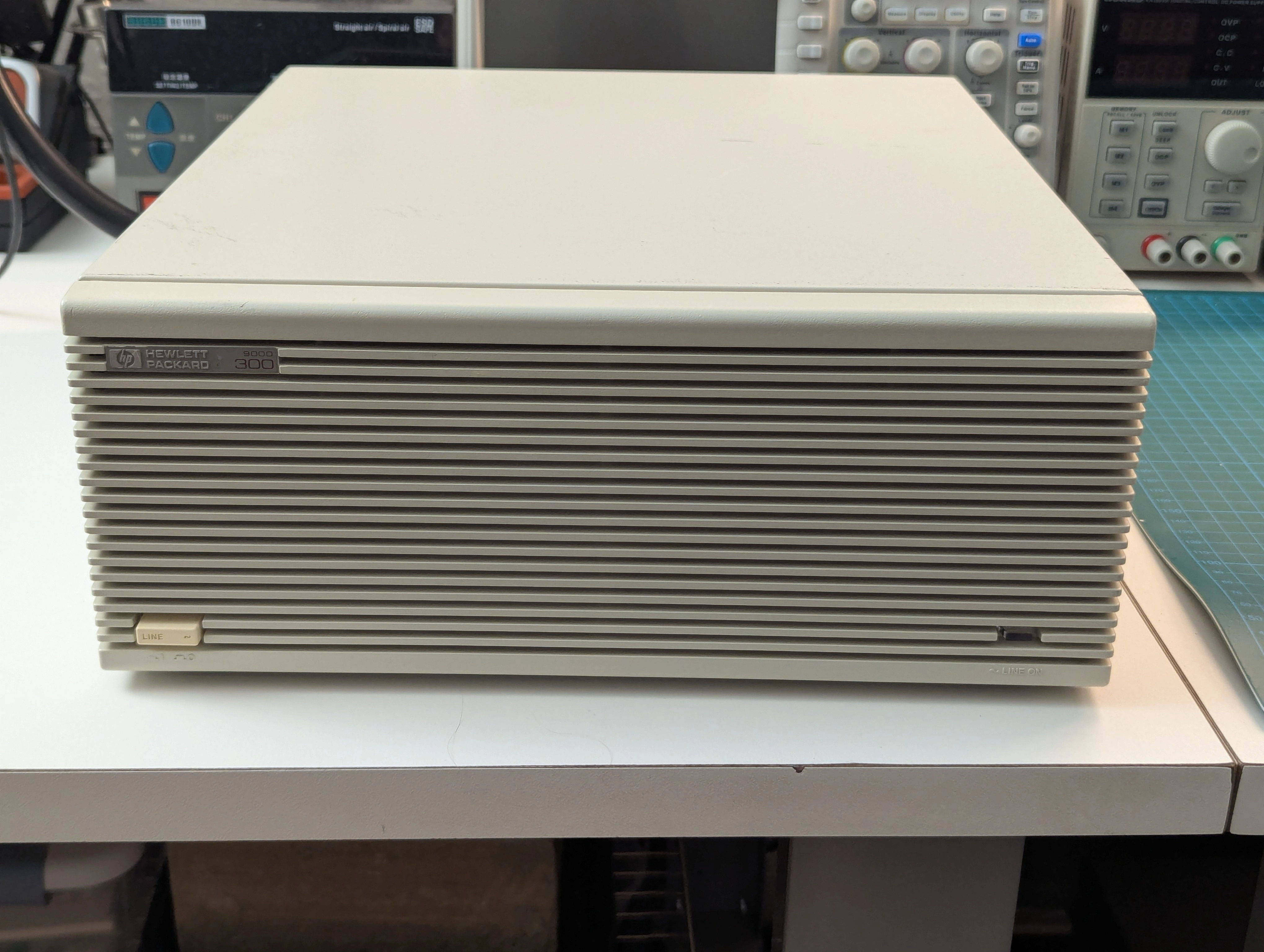
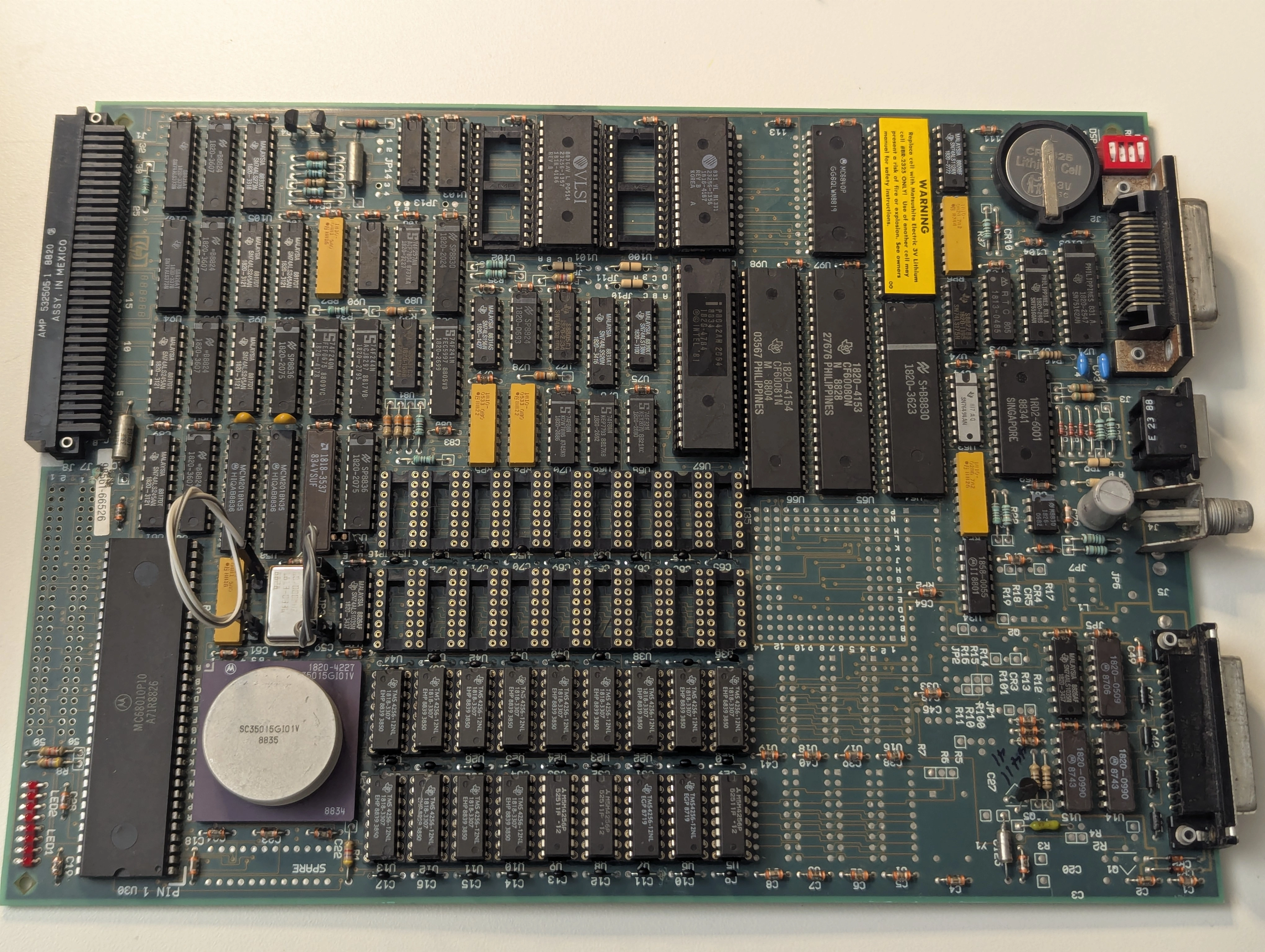
I recently acquired a couple of HP 98561A desktop computers, also known as the HP 9000 Model 310. This machine features a Motorola 68010 CPU clocked at 10 MHz, 1 MB of onboard RAM and a built-in HPIB/GPIB port for interfacing with test equipment and mass storage. One of them came with just the processor board and the other was configured with a 98624A GPIB board, a 98543A color video adapter and a 98257A 1 MB RAM board bringing the total RAM to 2 MB. Unfortunately the seemingly nicer one was a bit of a basket case.
Whoever owned this machine before me was not kind to it. The case had a significant amount of rust, all of the boards were extremely dirty and even had rusty chip leads in a handful of places. After a deep clean I reassembled the machine and attempted to power it up but the power supply just began clicking without any LEDs illuminated on the processor board. I checked the 5V rail and after seeing a spike to 35V I quickly unplugged the power supply and removed it from the machine. Clearly something was amiss.
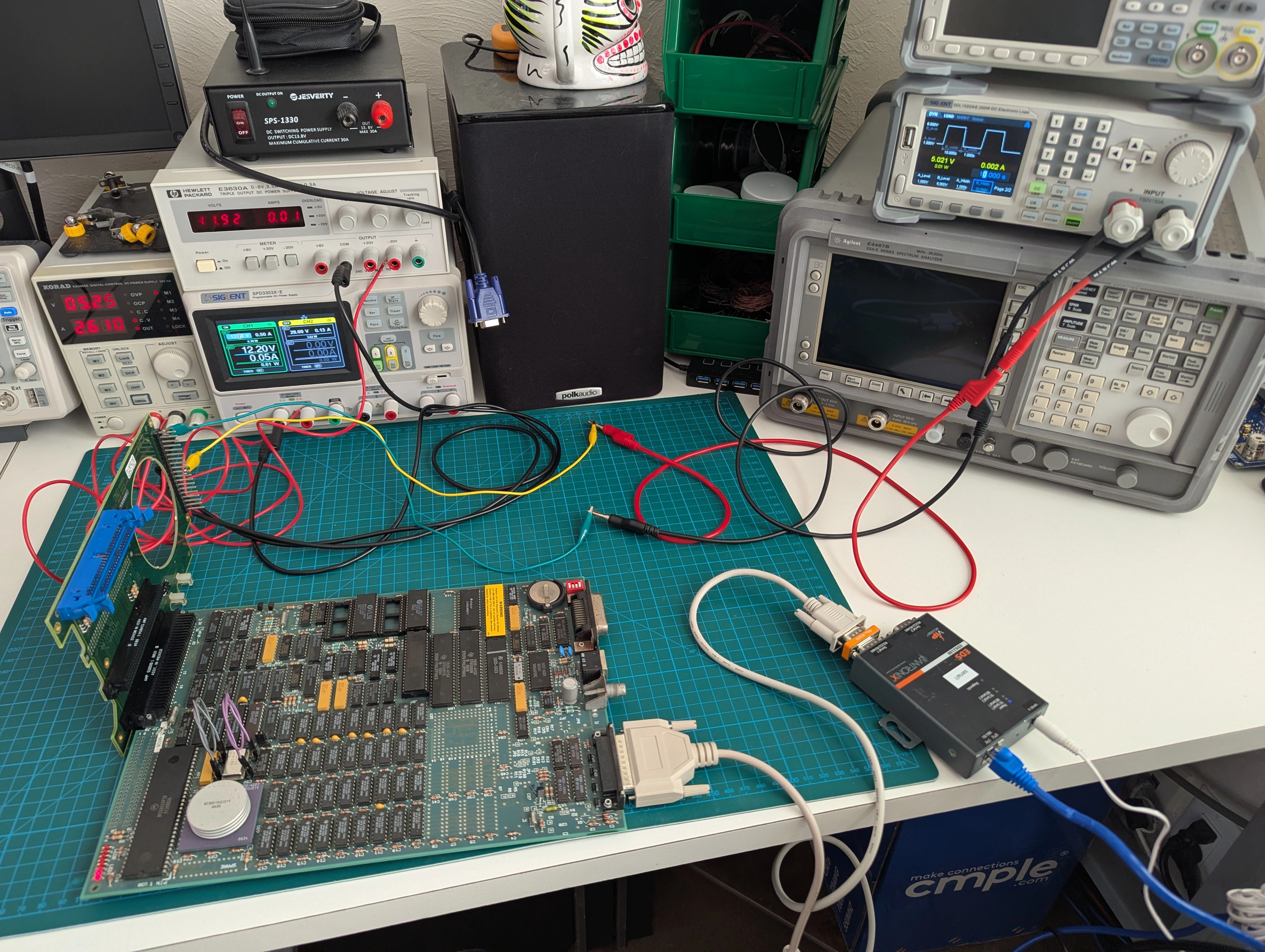
Before attempting to repair the power supply I wanted to evaluate the rest of the boards to verify whether they were damaged from the voltage spike or terrible storage conditions. The processor and video boards plug into what some of the HP documentation describes as the "motherboard" which is actually more of a backplane for power and data. The power supply normally outputs 5V, 12V and -12V (full pinout available in HP A-98568-66501-4).
I rigged up my bench power supplies to provide the needed voltages and was happy to see 8 red LEDs lit up on the processor board. 35V on the 5V rail hadn't killed it entirely after all.
After spending a bit of time with datasheets and other documentation I found that the power supply was responsible for pulling the reset line low and starting the boot process after voltages stabilize. I manually initiated a reset by grounding the reset line, the CPU successfully started executing code off the boot ROMs but it would almost immediately halt the boot process with the diagnostic LEDs showing 10000100: "top RAM test failure". Looking over more documentation as well as the boot ROM source code I was able to figure out that on startup the machine executes a memory test on the top 16 KB of RAM to determine if the rest of the code can be successfully loaded. Our RAM was apparently so bad that the first test was failing before video or serial was initialized.
At this point the HP documentation recommends replacement of the processor board and has no useful information on repair:
Field Repair Philosophy for the Series 300 Computers and the HP 98568 Bus Expander is assembly level. This means that when a failure occurs, the problem is diagnosed to the assembly having the failed part. That assembly is then replaced. Replacement assemblies are available through local HP Sales and Service Offices.
Thanks HP. I almost want to call up my local HP Sales and Service Office (assuming it isn't just some global 800 number you call now) and try to order part number 98561-66526 just to see what they say.
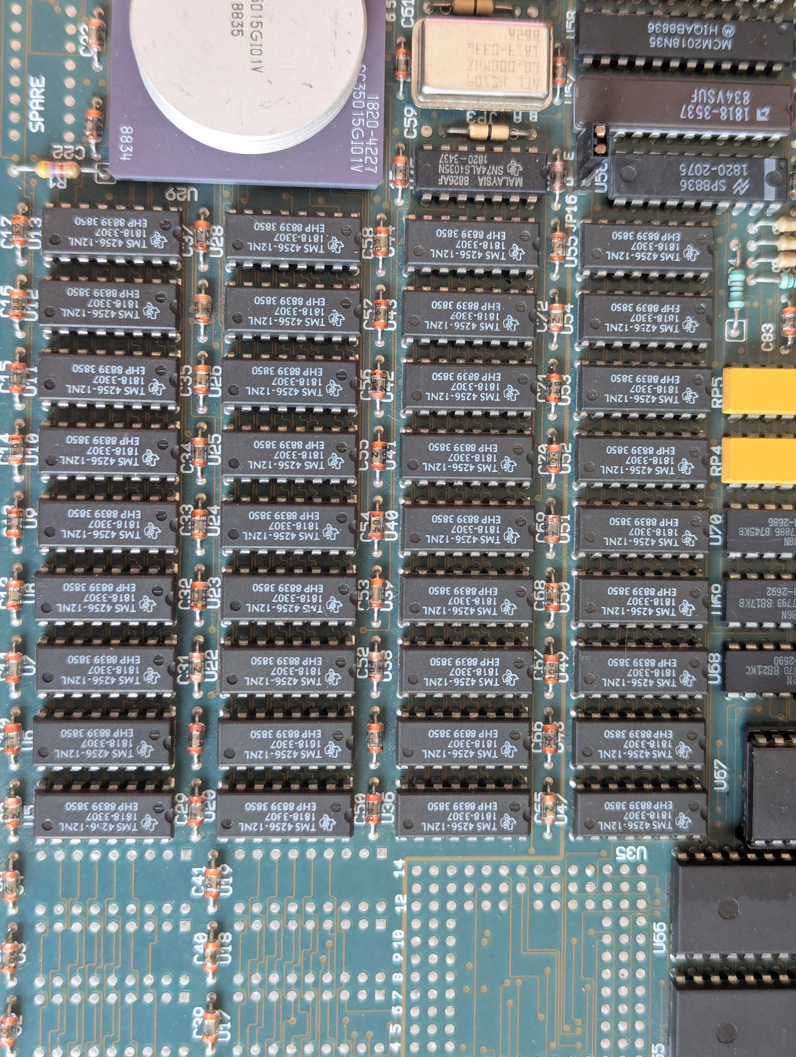
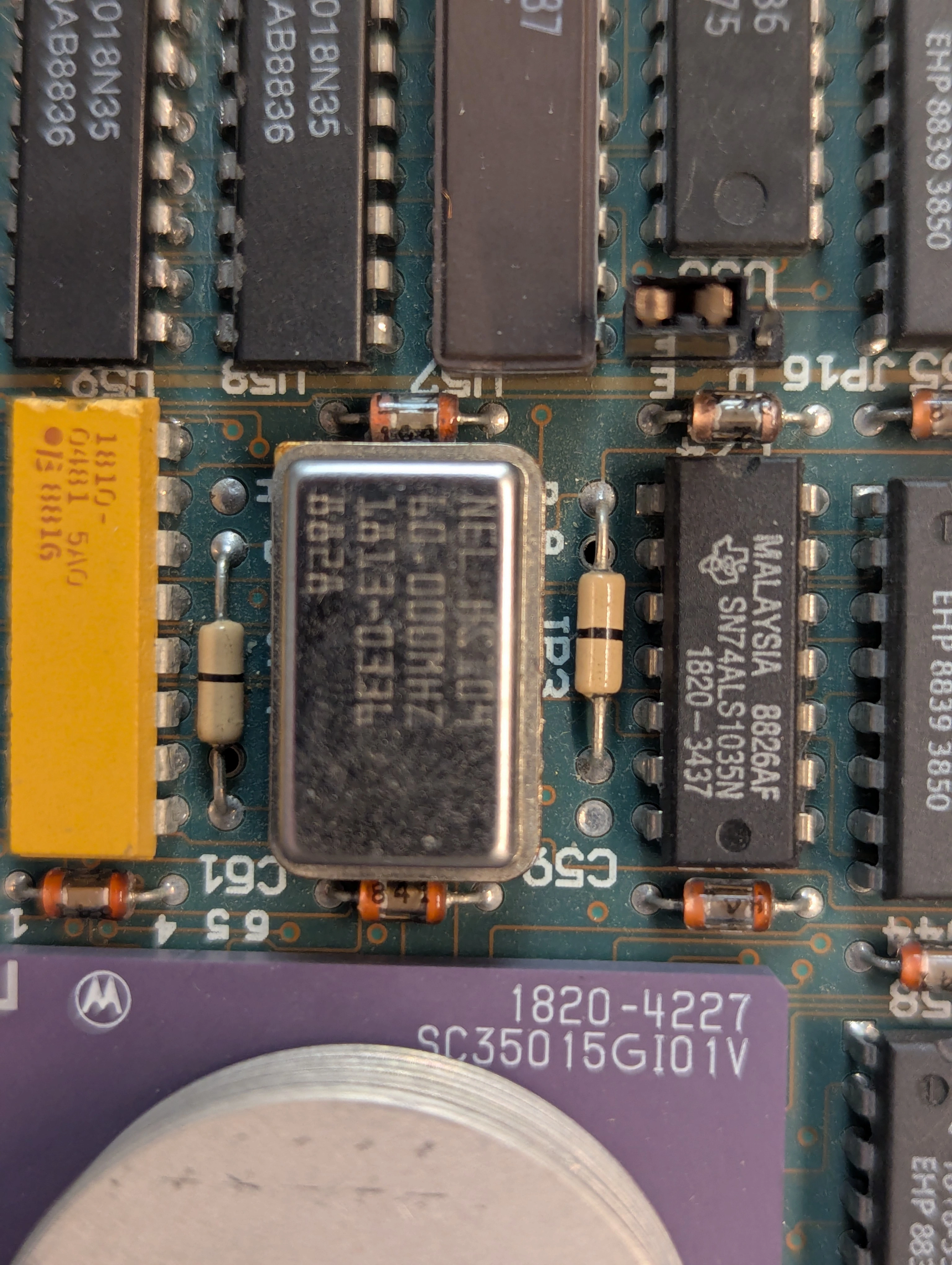
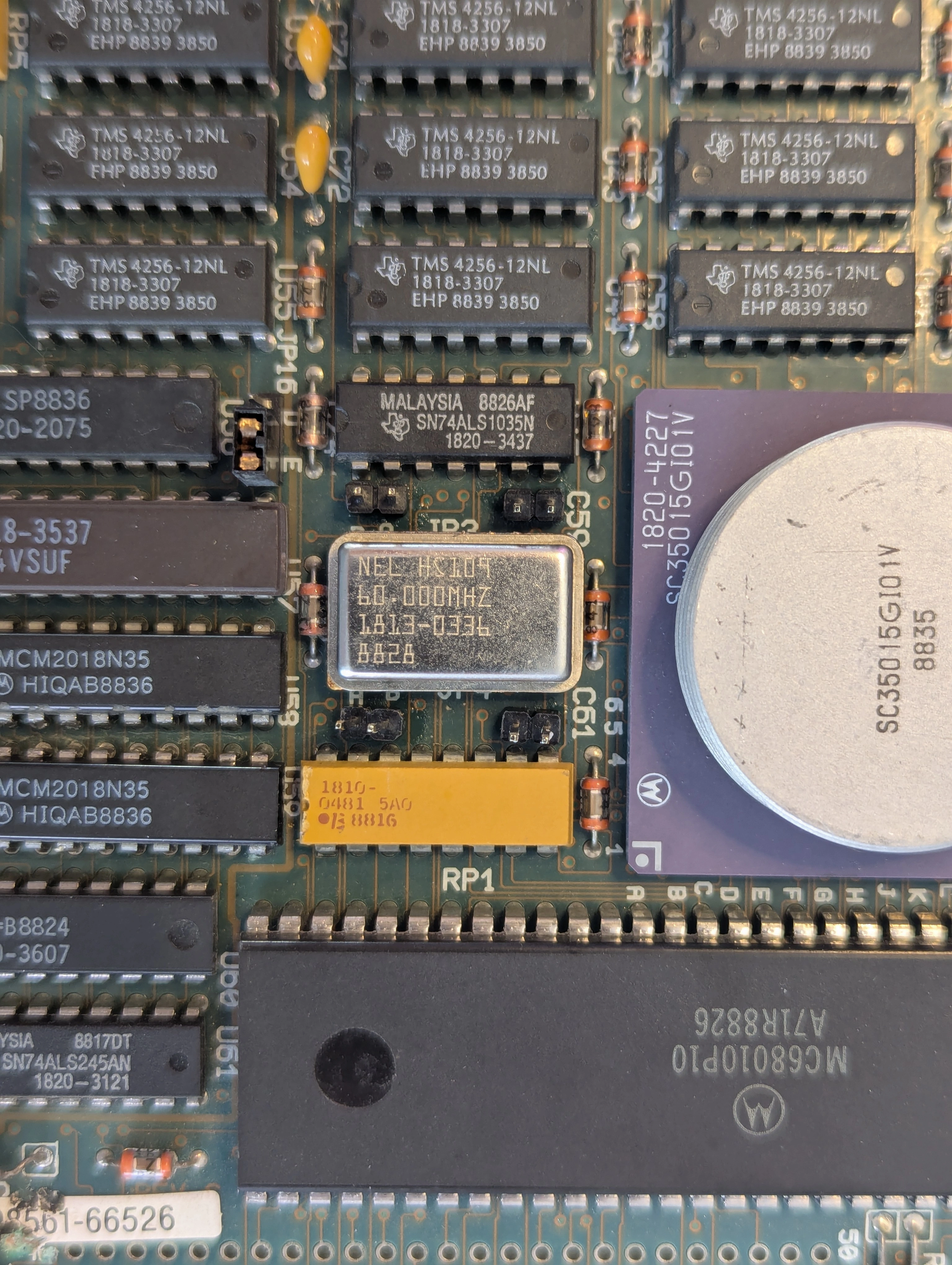
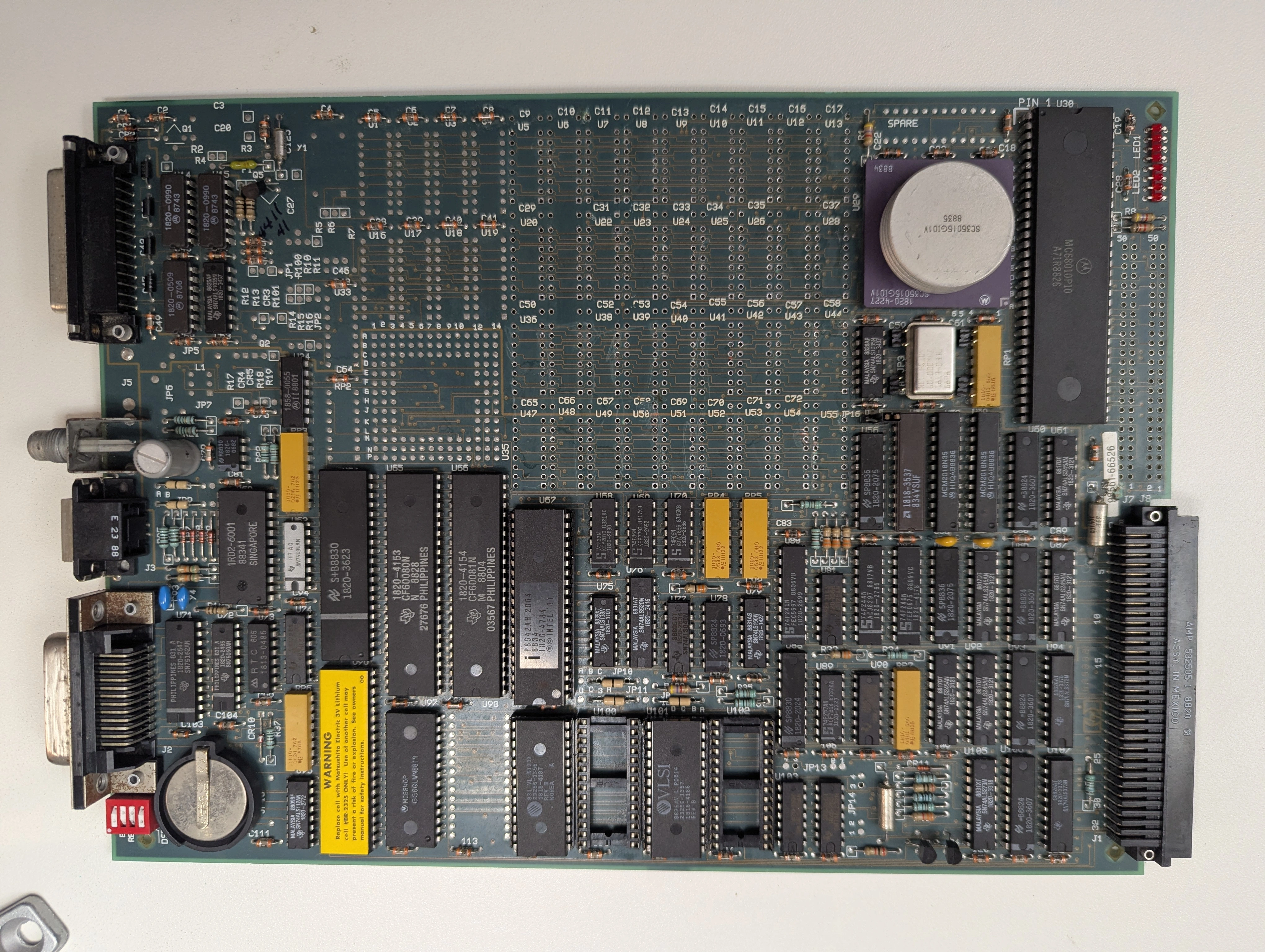
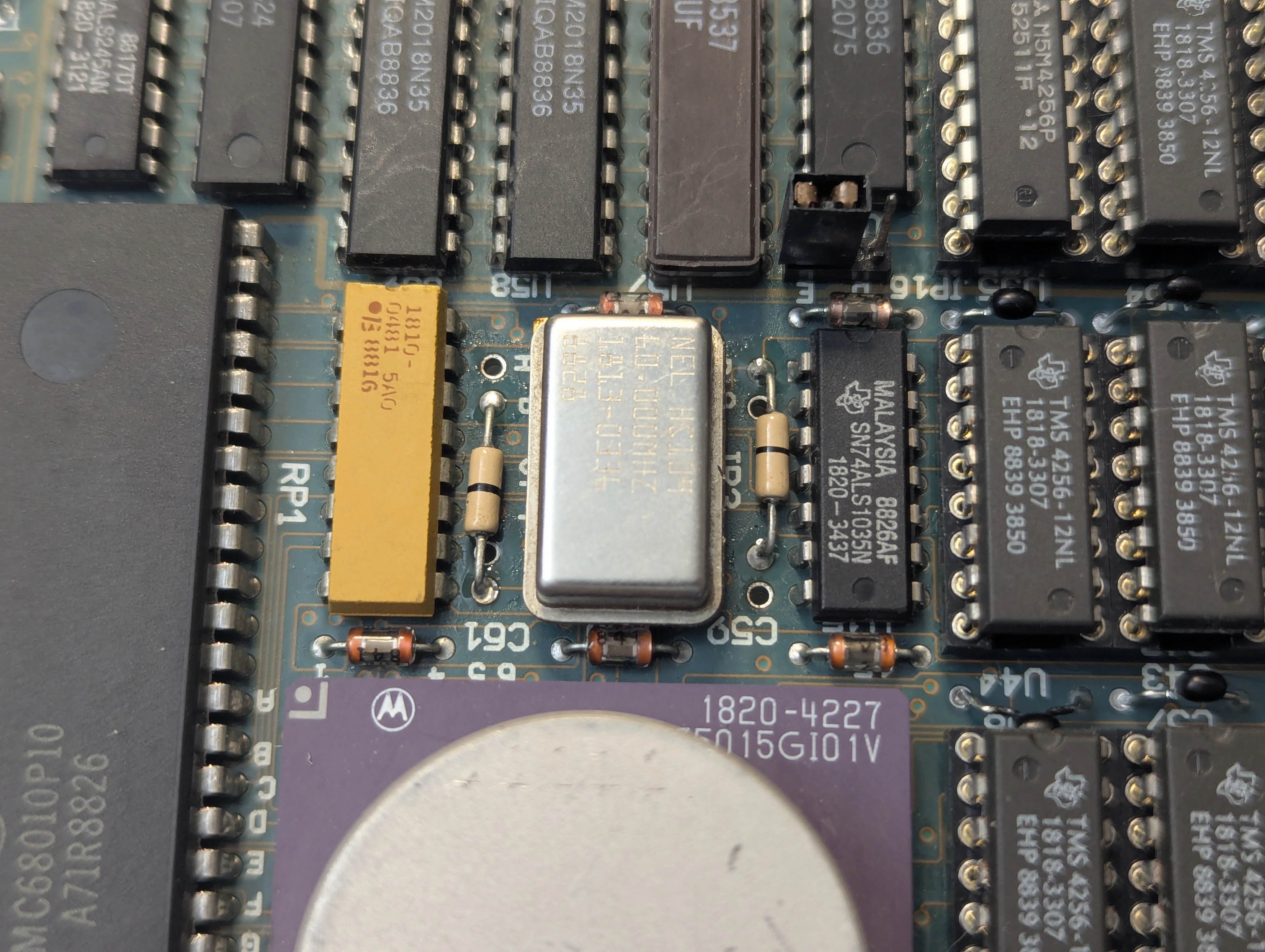
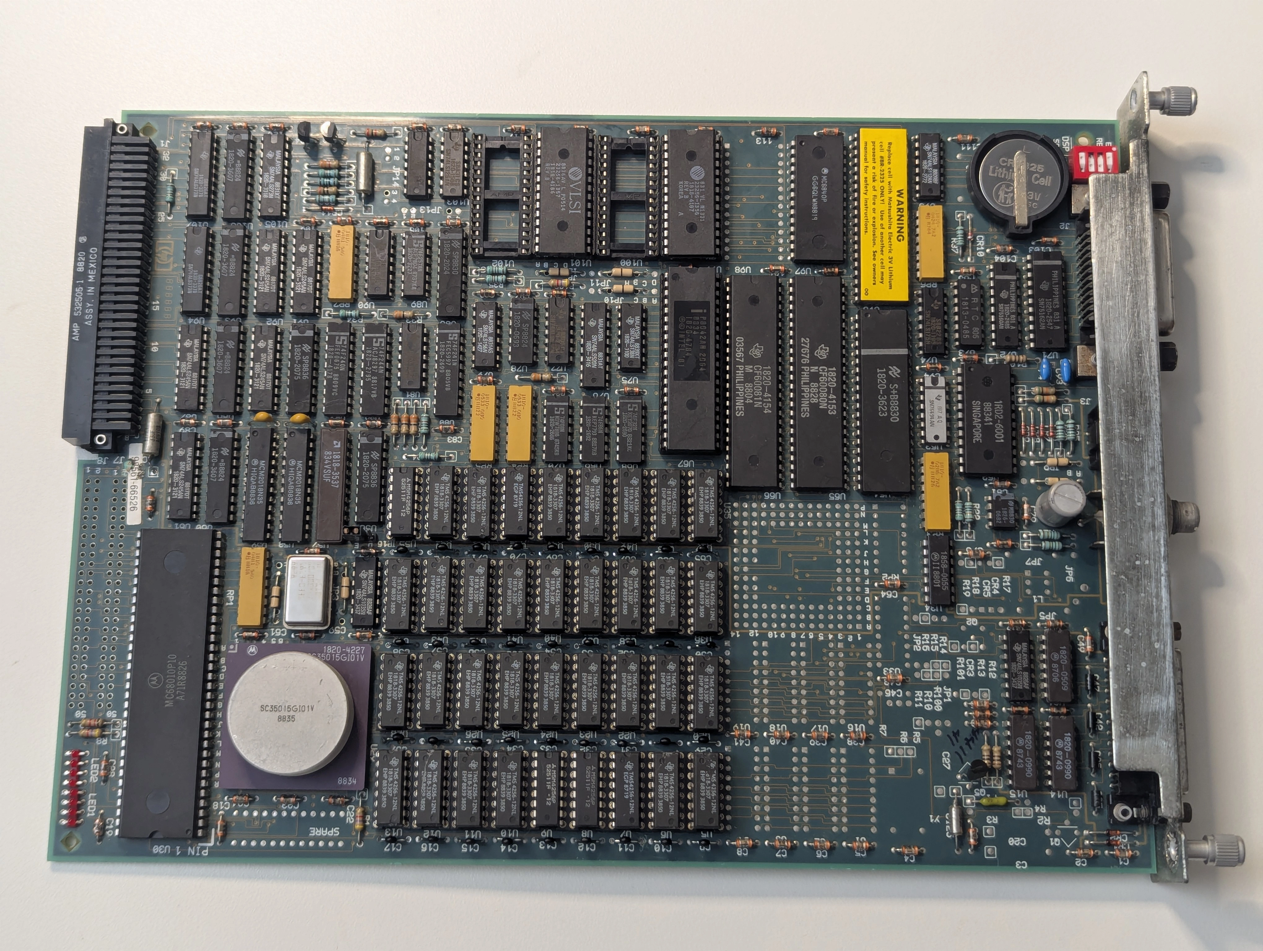
While a fair bit of internal HP documentation is now available for these machines, including full source code for the boot ROMs, schematics have not been published. HP drawing E-98561-66512-4 would be particularly helpful but does not seem to be available on the internet. I downloaded some datasheets for both the 68010 and TMS4256 chips and went over the board but all signals looked as they should. One of the useful things I discovered buried in HP manuals and documentation (A-98561-66512) was that jumpers JP3 and JP4 control how much memory the board is configured to use, though the actual settings aren't provided. I removed the 0 ohm resistors and replaced them with pin headers then experimented with different configurations to identify if anything had an effect.
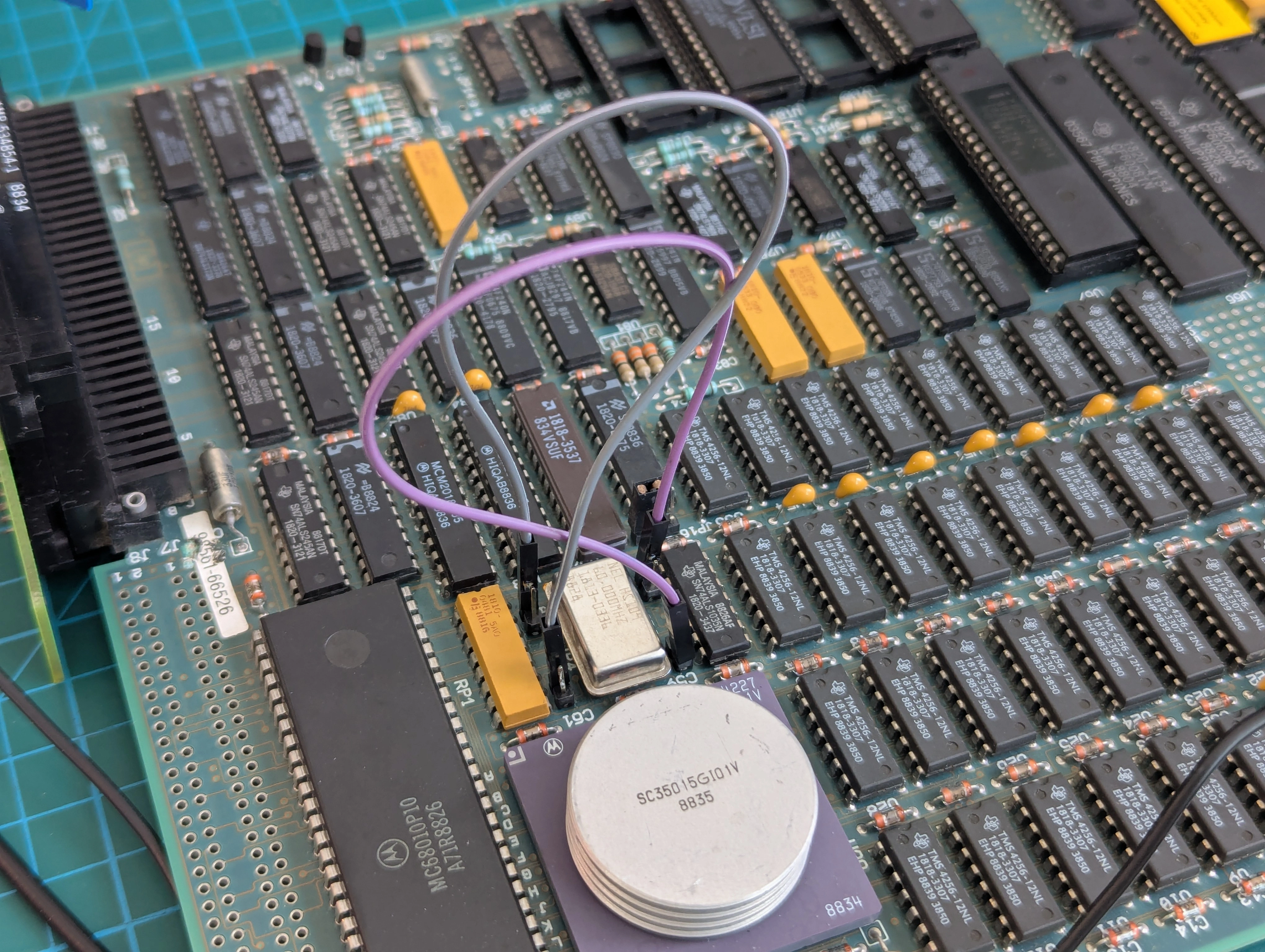
Changing J4 to the "A" position configures the board to only use half the available RAM and resulted in the machine getting quite a bit further through the boot process, far enough to begin outputting data over the RS-232 port!
I hooked up a terminal and was greeted with:
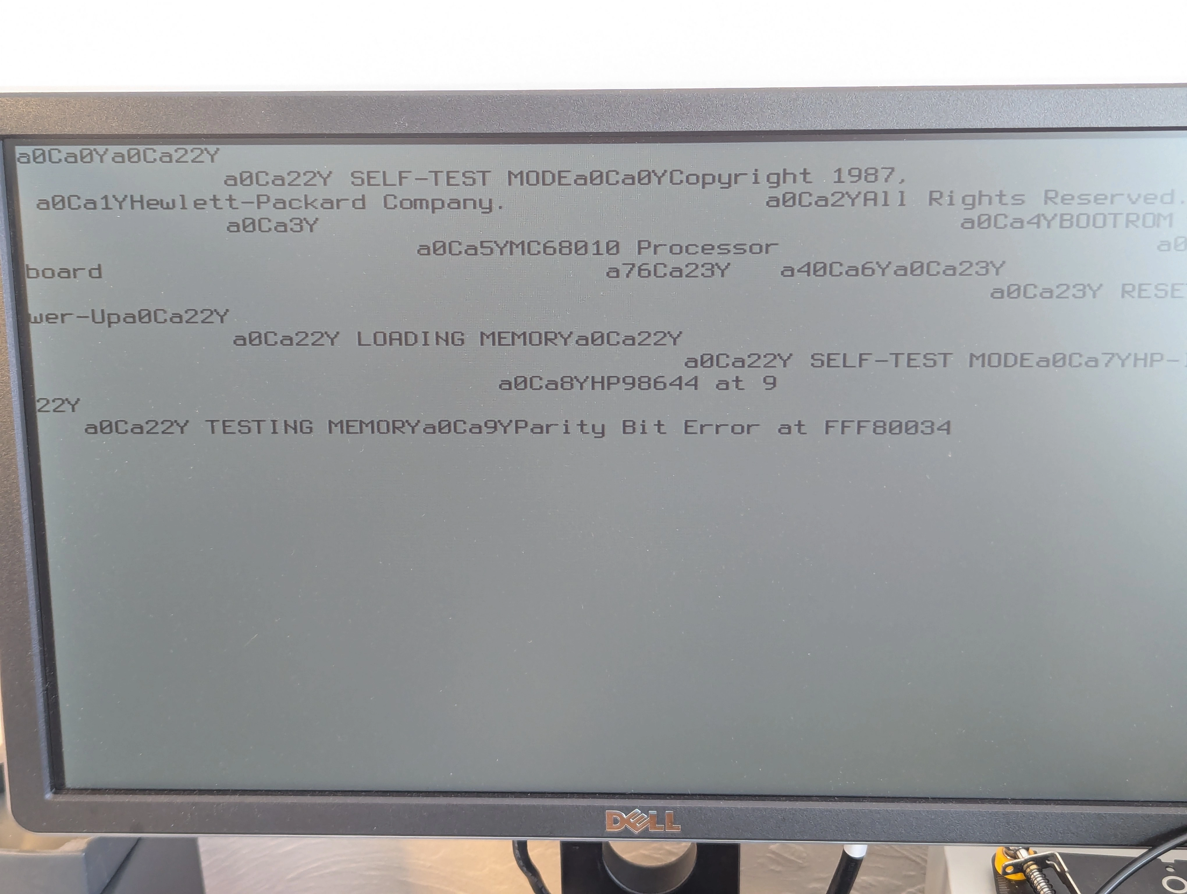
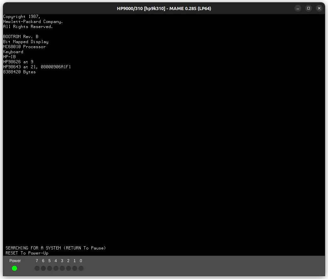
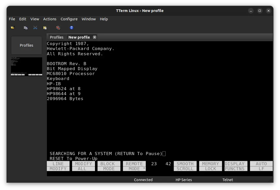
The text was garbled because the serial output includes control codes for the HP 2392A terminal which are unsupported on the terminal emulator I used. Startup output with the control codes stripped:
Copyright 1987,
Hewlett-Packard Company.
All Rights Reserved.

BOOTROM Rev. B
MC68010 Processor
Keyboard

 RESET To Power-Up

 LOADING MEMORY

 SELF-TEST MODE
HP-IB
HP98644 at 9

 TESTING MEMORY
Parity Bit Error at FFF80010
I set things up to reset the machine a few times a minute and log the locations of bit errors overnight to look for patterns. After running for about 12 hours I found that the machine always failed the memory test on random locations between FFF80000 and FFF8049C. A few specific locations seemed to be favored, otherwise no real patterns emerged from the data in the morning when I processed the boot logs. The memory test always failed and it always failed pretty much immediately after starting the test.
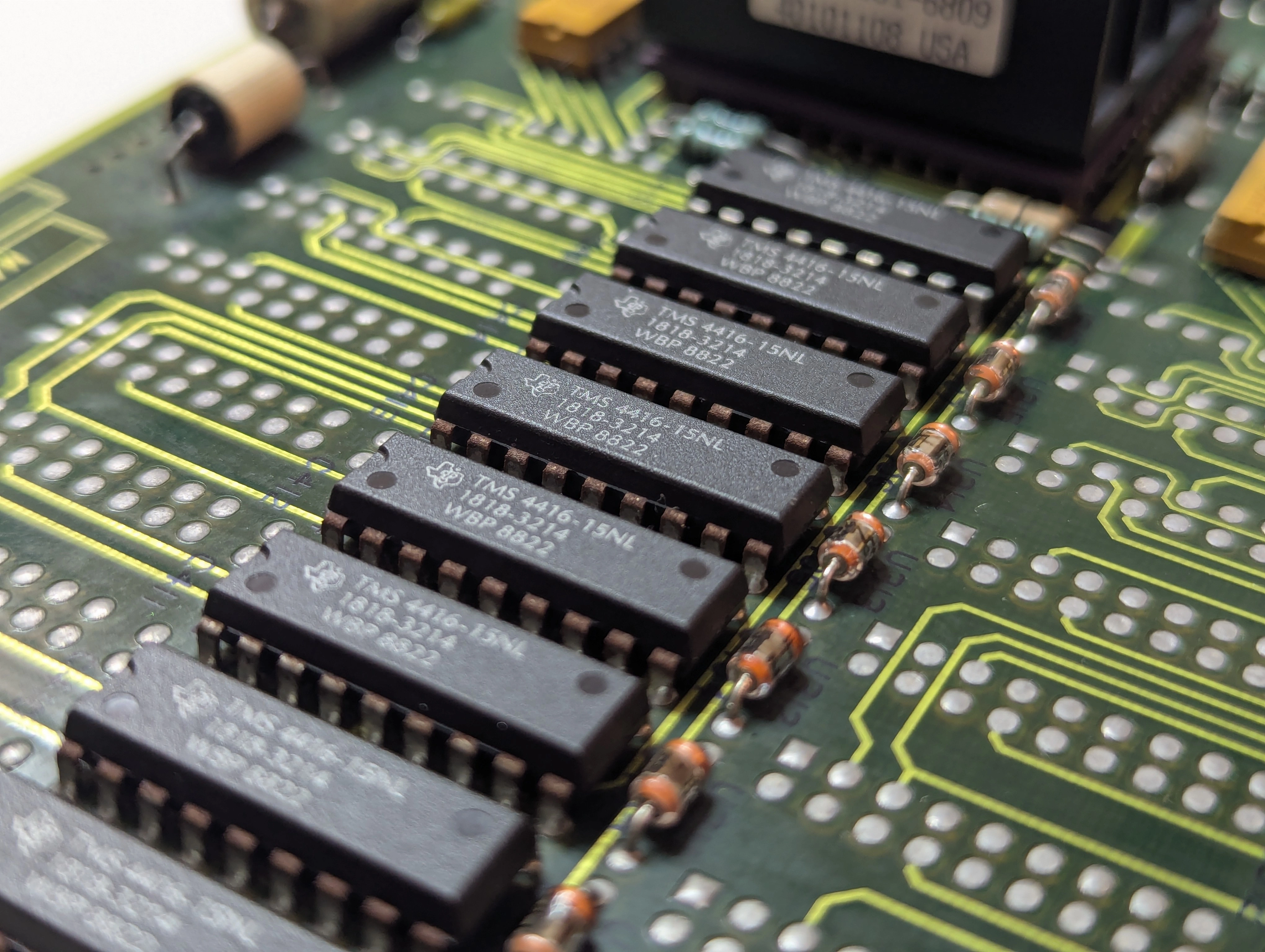
At this point the machine was only configured to use 512 KB of RAM and still wasn't fully booting but I was still happy to get text on a screen with the condition it was in when I received it. Ultimately my goal is to get this thing to boot to BASIC so we're not done yet though. Putting together everything I know so far I was strongly suspicious of the RAM chips on the board given that no traces appear to be broken and all the signals I could identify looked fine on the scope. It seemed probable that the one bank which would partially boot the machine had fewer failed chips than the other bank.
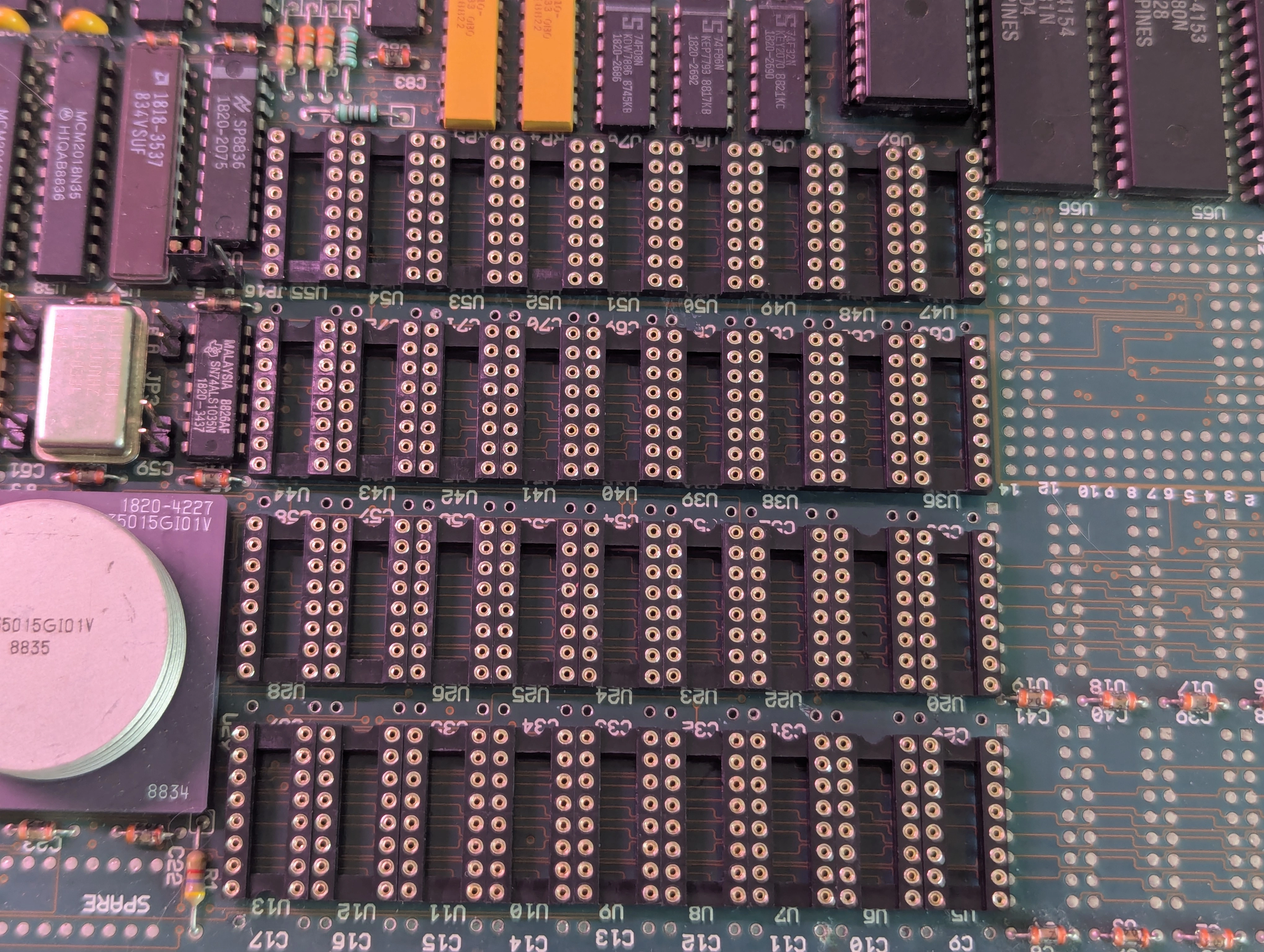
Replacing at least some of the RAM chips was going to be required but HP in their infinite wisdom not only saw fit to solder all of these chips in place, they also bent all of the pins! Clearance between the chips is minimal as well, the first sockets I ordered didn't fit properly because of how tight everything is on the board. Getting all the chips cleaned up and ready to fit into the rather poor quality sockets was also very tedious and time consuming.
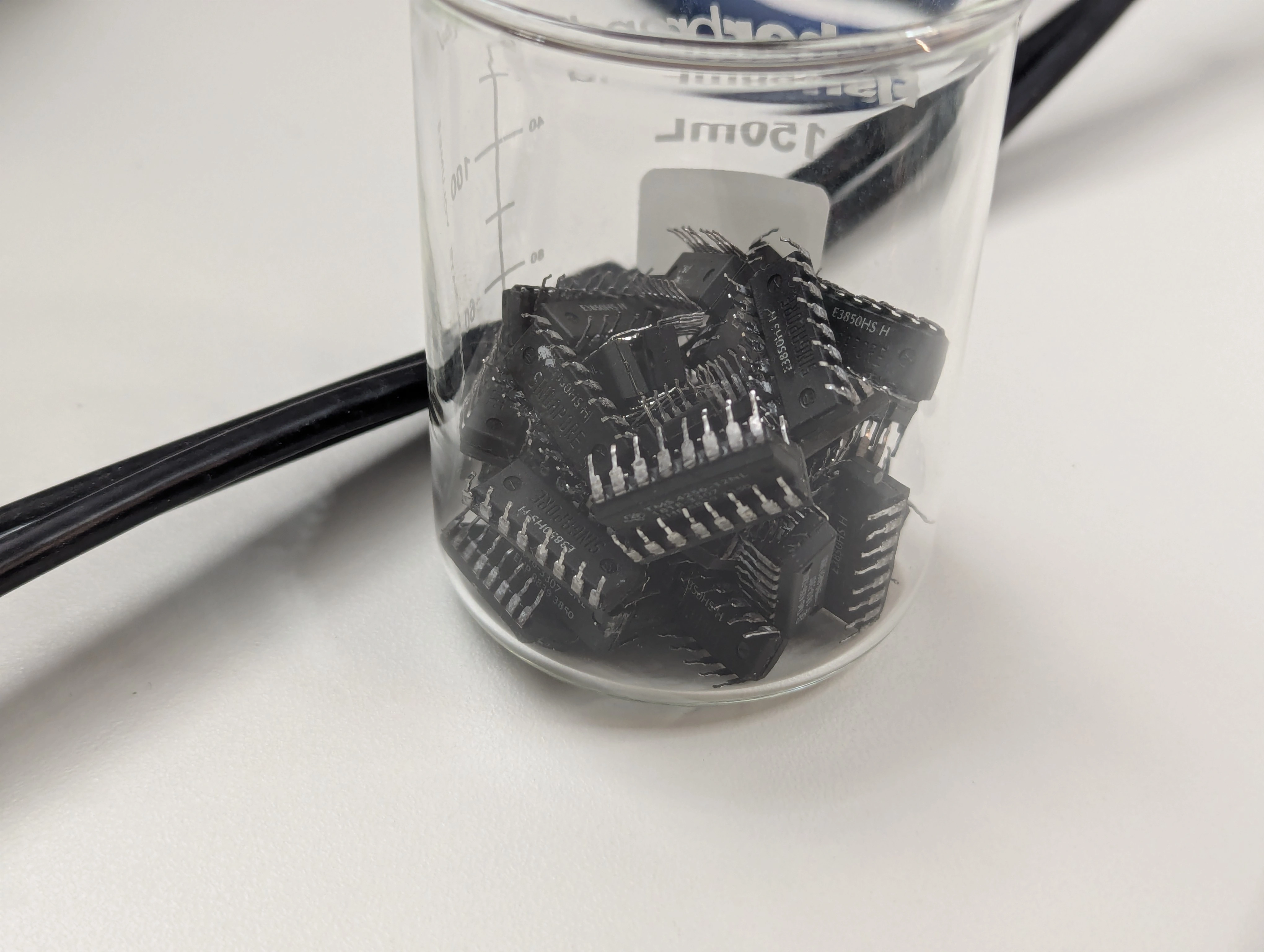
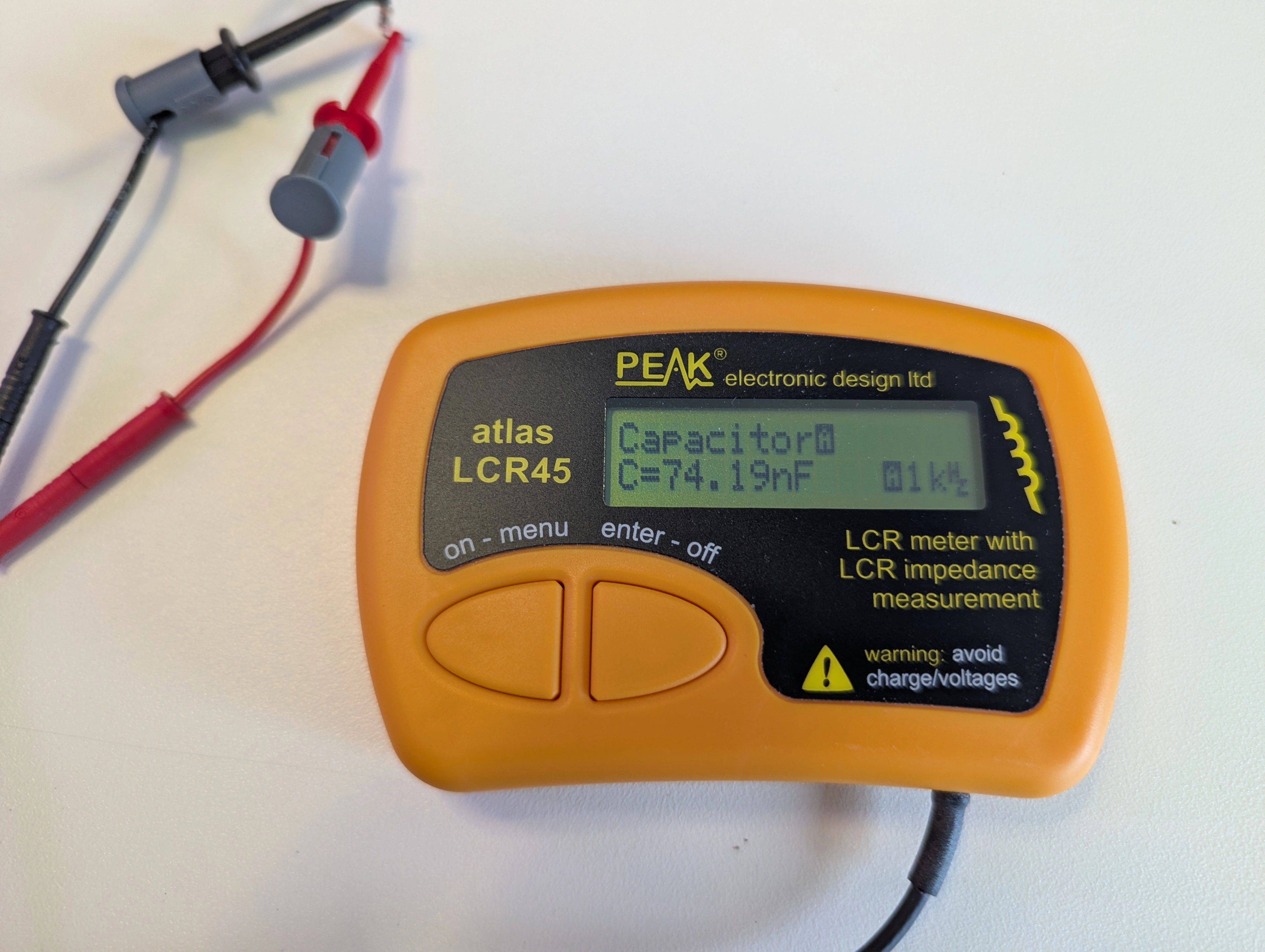
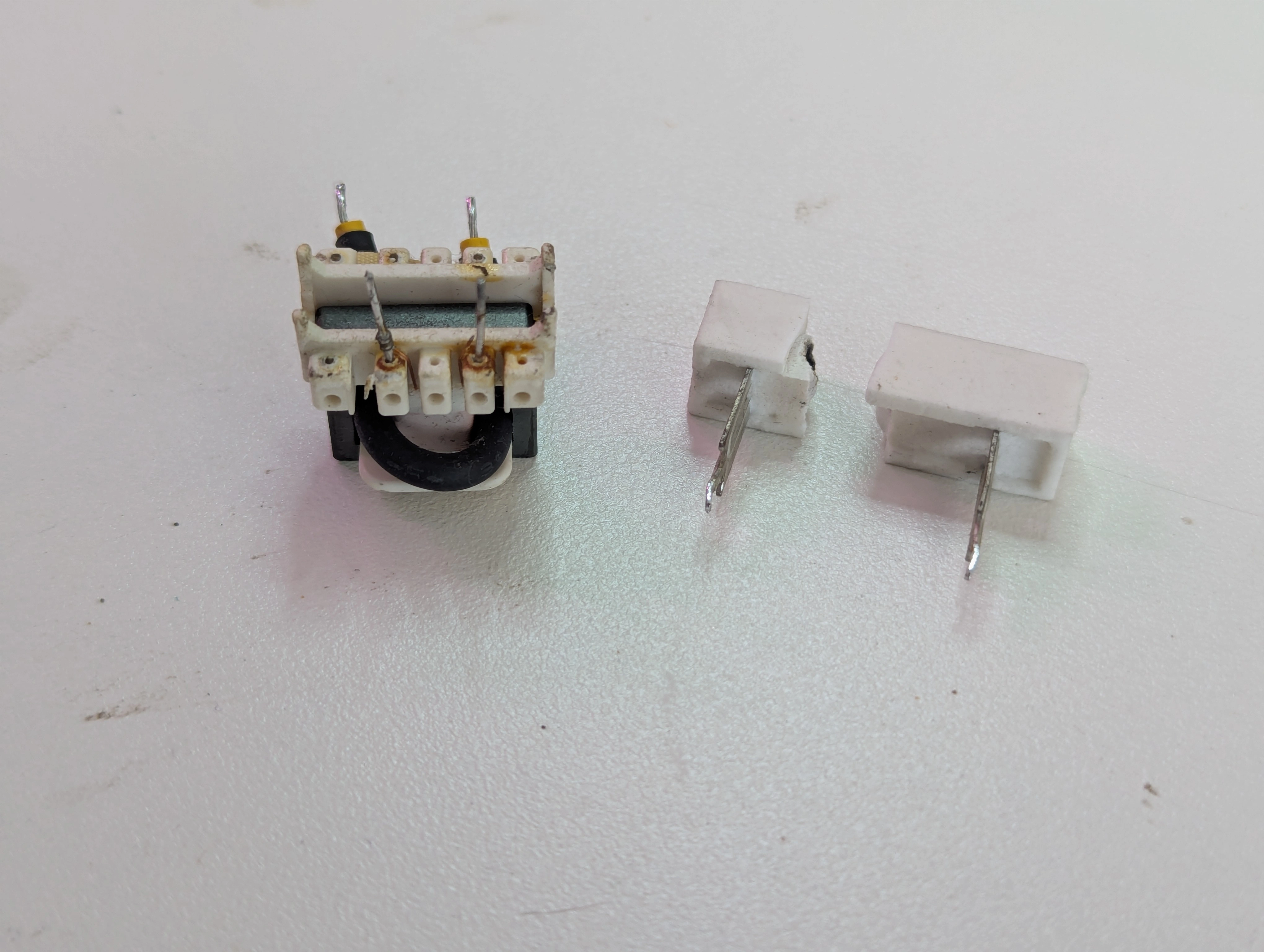
While I was desoldering half the board anyway I removed the filter caps for the RAM chips. Many were low but still within tolerance, plenty were well below 100nF however:
After the sockets and caps arrived I got them soldered in and left the board configured for 512 KB of RAM. To make swapping chips in easier I used a different style socket stacked on top of the soldered-in sockets as the style of socket that actually fit on the board was kind of a pain to use. Thankfully I got lucky with the first set of chips I picked for the test and the board booted right up when I gave it power! Several hours of desoldering and soldering was not for nothing 🎉🎉
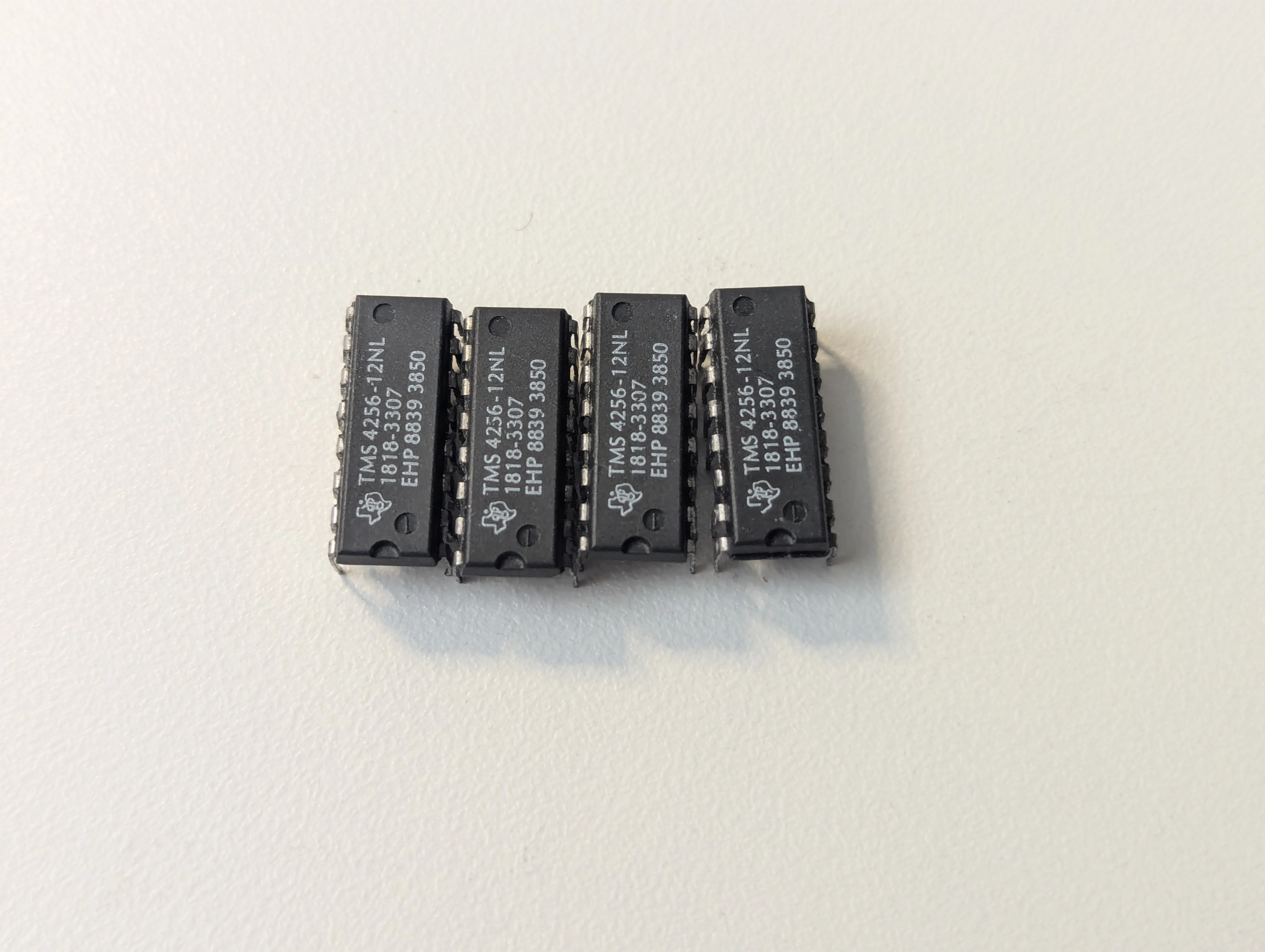
From here it was just a matter of swapping around chips and running the RAM test until I was able to identify all of the bad chips. Ultimately four of them were found to have problems so it is little wonder this board was not able to boot up.
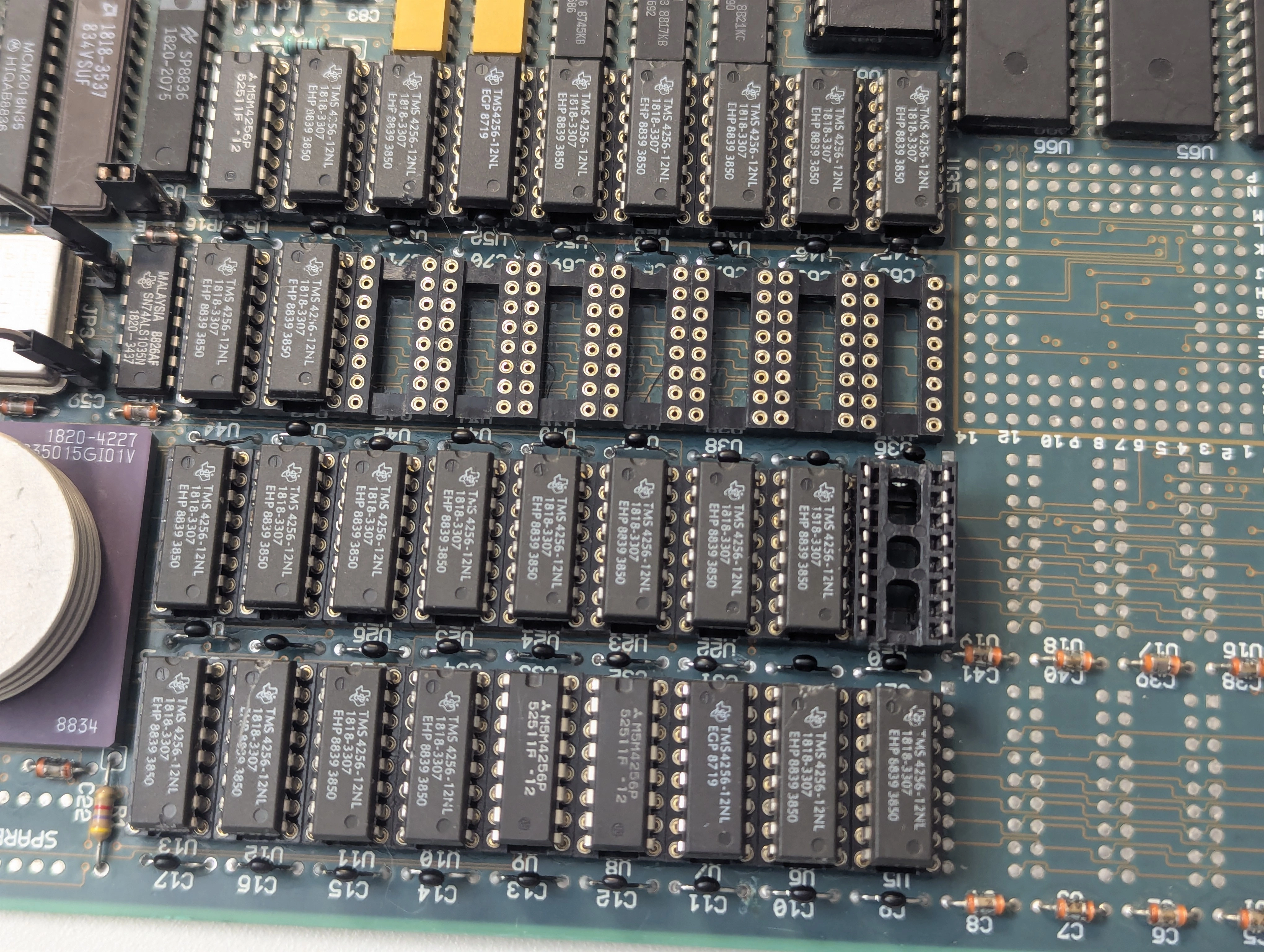
The last item was to remove the temporary headers and reinstall the original jumpers for the RAM configuration.
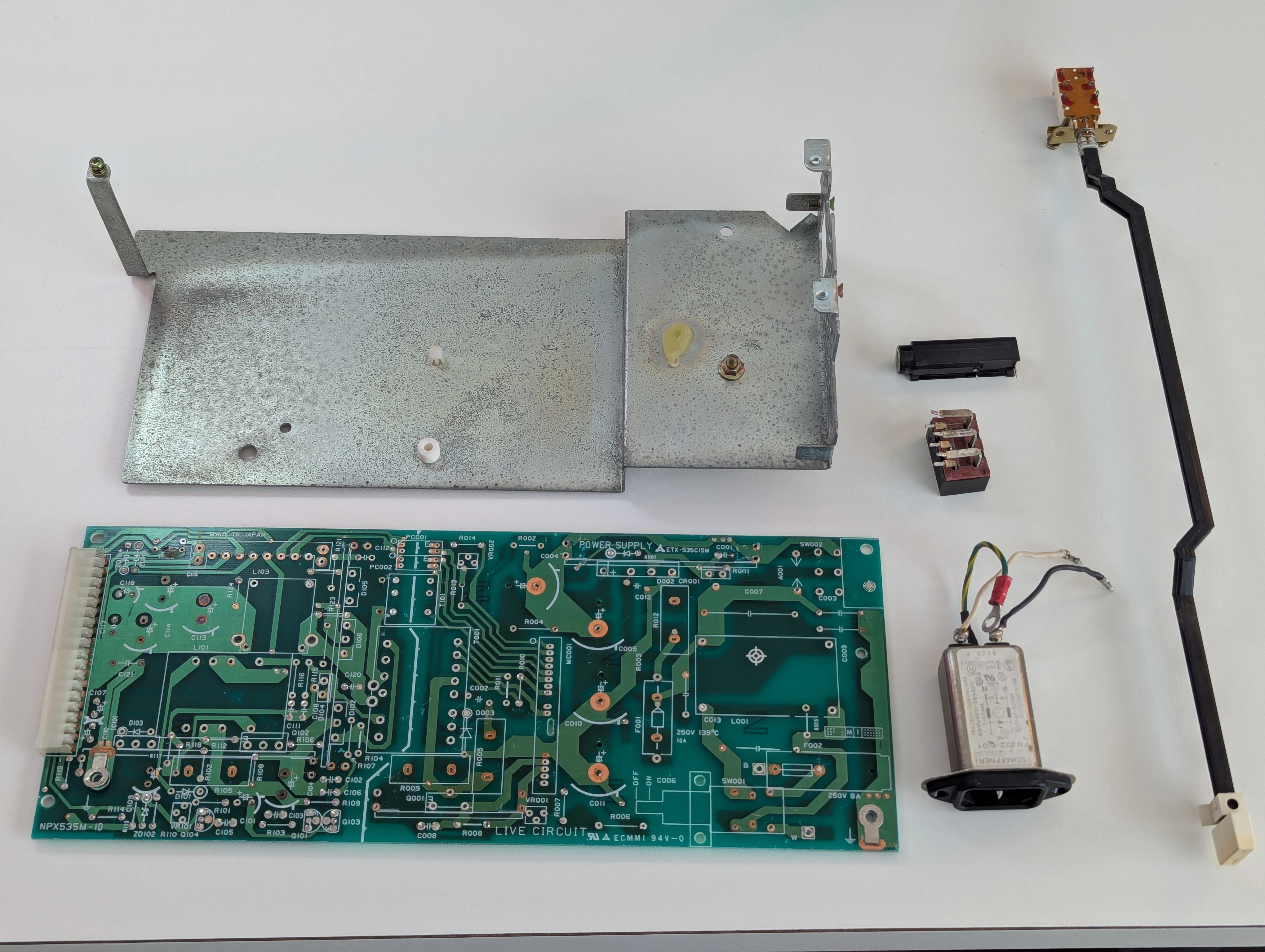
While waiting on the sockets for the processor board I attempted to start troubleshooting the power supply but didn't get very far before multiple components let the magic smoke out. Water had definitely made it into the power supply and I think rust and other corrosion shorted out some components causing them to fail. Without schematics I was stuck with the repair given how many components had failed, not that repair was likely to be cost effective compared to replacement anyway.
I stripped down the failed power supply to recover as many good parts as I could, all of the big filter caps tested fine though a few showed corrosion on the leads and were disposed of. I kept the PCB and associated bits since removing it altogether would leave a big hole in the front of the machine where the switch is. I don't care much about keeping the power supply internals original but a hole in the front where the switch was isn't going to suffice.
The only real complication with replacing the power supply was ensuring the reset line goes low on startup to tell the CPU to start booting, otherwise it was just a matter of getting 5V, 12V and -12V to the correct places.
WIP
WIP
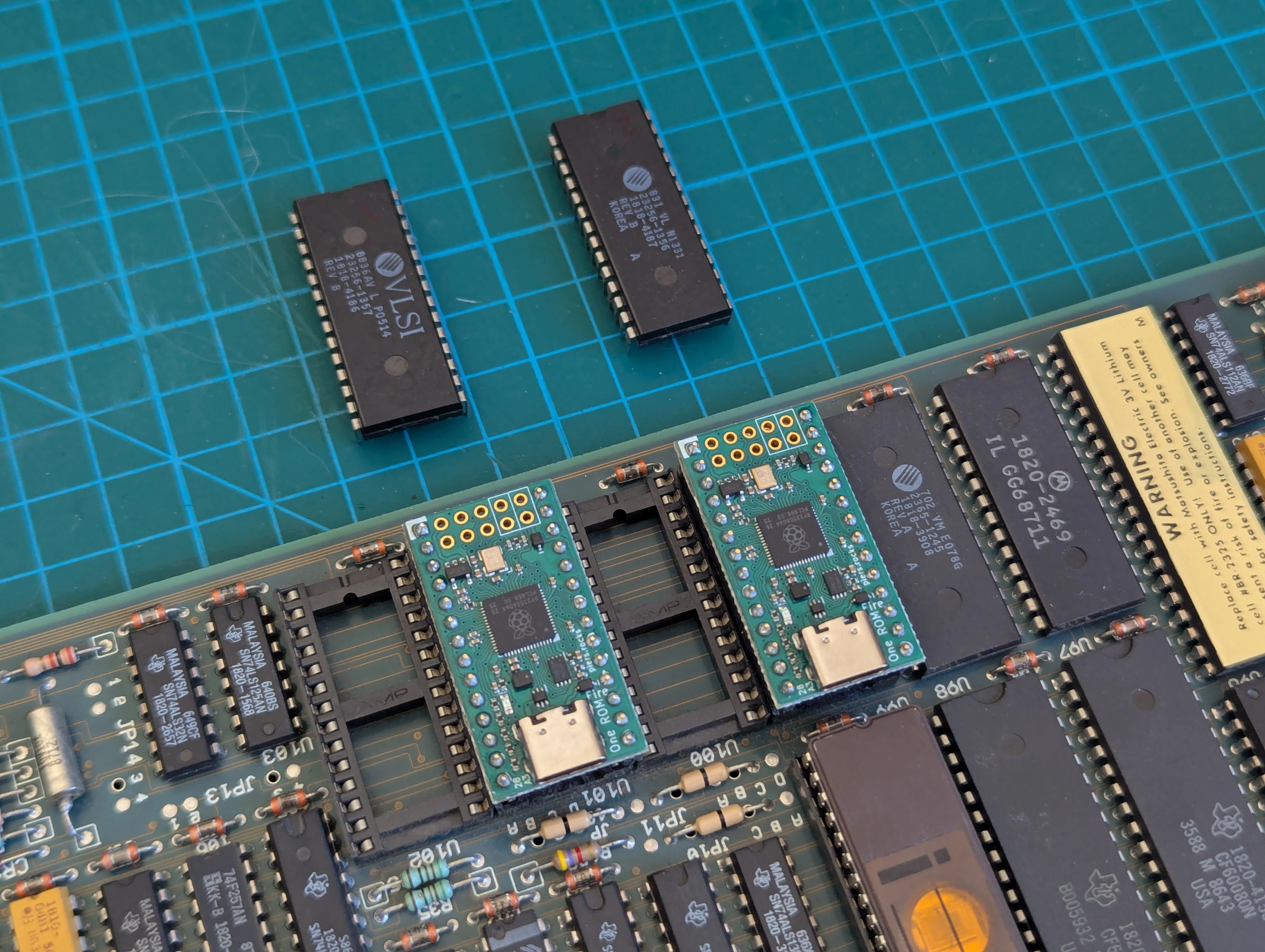
For fun I read the boot ROMs (1818-4186, 1818-4187) since only the rev A boot ROMs seem to be available for download online. Both ROMs read as AT28C256 chips with my T48 programmer. MAME complains about the checksums but loads and boots the ROMs just fine:
The boot ROM image is stored across both chips with one handling the lower eight bits and the other handling the upper eight. Merging and disassembling for further inspection:
$ srec_cat -o rev_b.bin -binary 1818-4186.bin -binary -unsplit 2 0 1818-4187.bin -binary -unsplit 2 1
$ strings rev_b.bin | grep BOOTROM
NuBOOTROM Rev. B
$ m68kdis -010 rev_b.bin
$ grep BOOTROM rev_b.bin.s
00001f26   424f4f54524f4d205265762e2042	L304	DC.B	'BOOTROM Rev. B'
I was able to load the ROM images onto a couple of One ROM boards. When programming them for this machine select ROM type 23256 and set both CS1 and CS2 active low. From here uploading a modified firmware will be trivial...
I don't have a HP 2392A terminal so right now I am using a Lantronix EDS2100 Serial-to-Ethernet device with TTerm to connect to the 310. TTerm is closed source but seems to be one of the few terminal emulators that has any support for 2392A control codes.
The BASIC command WRITEIO with the parameter ("select code") 9826 writes a byte of data directly to the specified memory location. Both the second and third parameters are interpreted as a decimal number. The LEDs are at memory address 0x0001FFFF. Here's a quick BASIC program that will count through all digits from 0 through 255 on the LEDs:
10 E=256
20 I=0
30 WHILE (I<E)
40 WRITEIO 9826,131071;I
50 I=I+1
60 END WHILE
70 GOTO 20
80 END